TTGO 32-Micro Learning from the Datasheet
Table of Contents
Before I start using a component, I try to soak up as much as possible about it in advance. These are my notes on the TTGO 32-Micro, by studying the datasheet(s):
I have written this without actually having one, so my findings might change/update once I try things out.
Overview
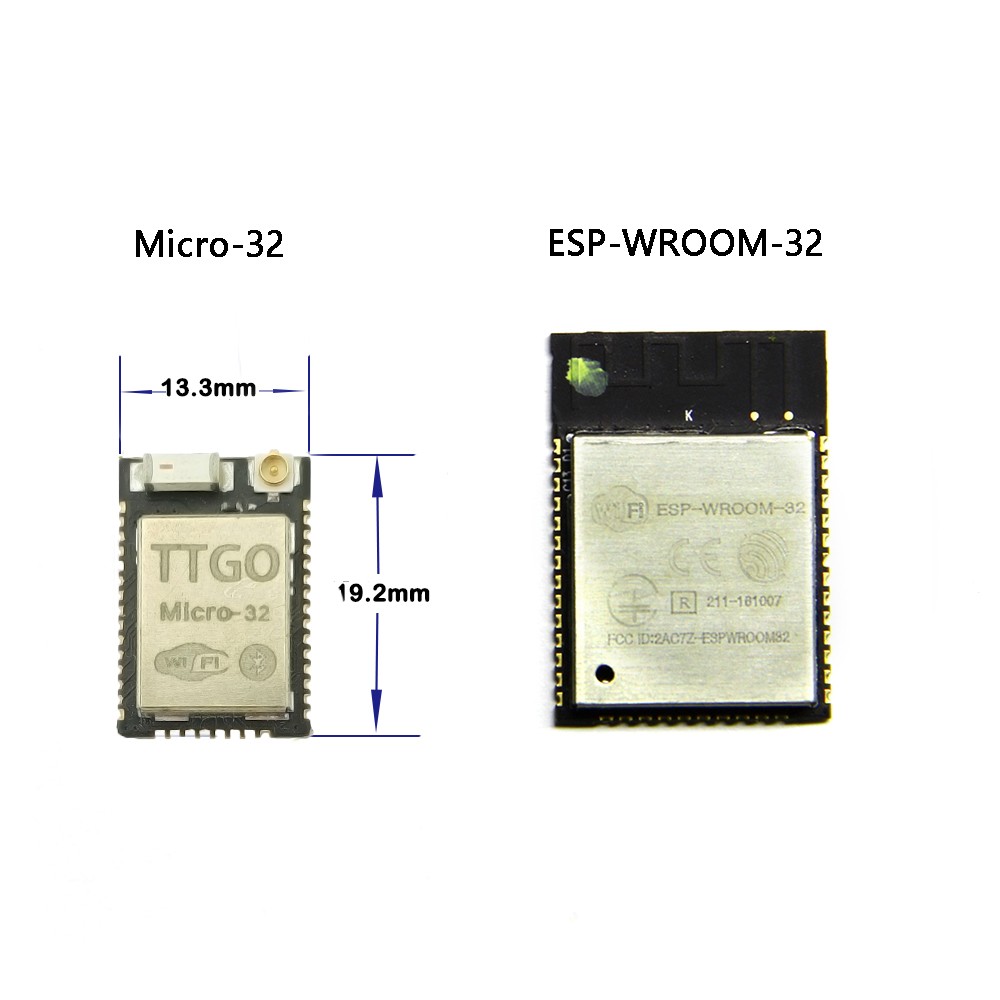
The TTGO Micro-32 contains an ESP32-PICO-D4 which is a System-in-Package (SiP) module that is based on ESP32 and also includes 4-MB SPI external flash and a 40 MHz crystal oscillator. This makes it an ideal candidate for projects with size constraints (e.g. a smartwatch).
The external flash part is a bit confusing as it is embedded into the ESP32-PICO-D4, so from that point of view it’s internal, but from the ESP32’s point of view it’s external. So we stick to external. :) (If you look at the schematics in the datasheet on page 13 you will see this makes sense).
If you look at my previous projects, you can see, that I’ve collected some experience with the ESP8266 based D1 mini, as well as the ESP8285 based M3 modules. This means I’m not entirely new to the ESP world, so I know there are a few things too look out for. For example Pins you shouldn’t use.
“Forbidden” Pins
As mentioned in the data sheet
Pins
GPIO16,GPIO17,CMD,CLK,SD0andSD1are used for connecting the embedded flash, and are not recommended for other uses. For details, please see Section 6 Schematics.
Which means, GPIO16 is internally wired to SPI flash /CS, as well as GPIO17 to SPI flash DO, so we will leave those untouched.
Also,
For connecting external PSRAM, SD3 (
GPIO10) is recommended for PSRAM_CS.
And, there is some magic going on with the strapping pins:
MTDI,GPIO0,GPIO2,MTDO,GPIO5
According to the datasheet they should be set the following way:
| PIN | Value | Reason |
|---|---|---|
MTDI (a.k.a. GPIO12) |
0 | Datasheet: “The operating voltage of ESP32-PICO-D4’s integrated external SPI flash is 3.3V. Therefore, the strapping pin MTDI should hold bit “0” during the module power-on reset.” |
GPIO0 |
0/1 | To program (0) or boot (1), a.k.a. download mode or SPI boot mode |
GPIO2 |
0/1 | Don’t care, see datasheet (only applicable if MTDI = 1, then set to 0 for download mode |
MTDO (a.k.a. GPIO15) |
0/1 | To enable (1) or disable (0) boot debug log on U0TXD |
GPIO5 |
0/1 | Depending on the timing of SDIO Slave, see datasheet, in combination with MTDO |
Especially the GPIO5 needs to be tested. So I’m not sure yet what needs to be done here.
As well as,
ENneeds to be pulled high to start, (pull low to reset)
This means we have to consider the GPIO diagram with a few additions:
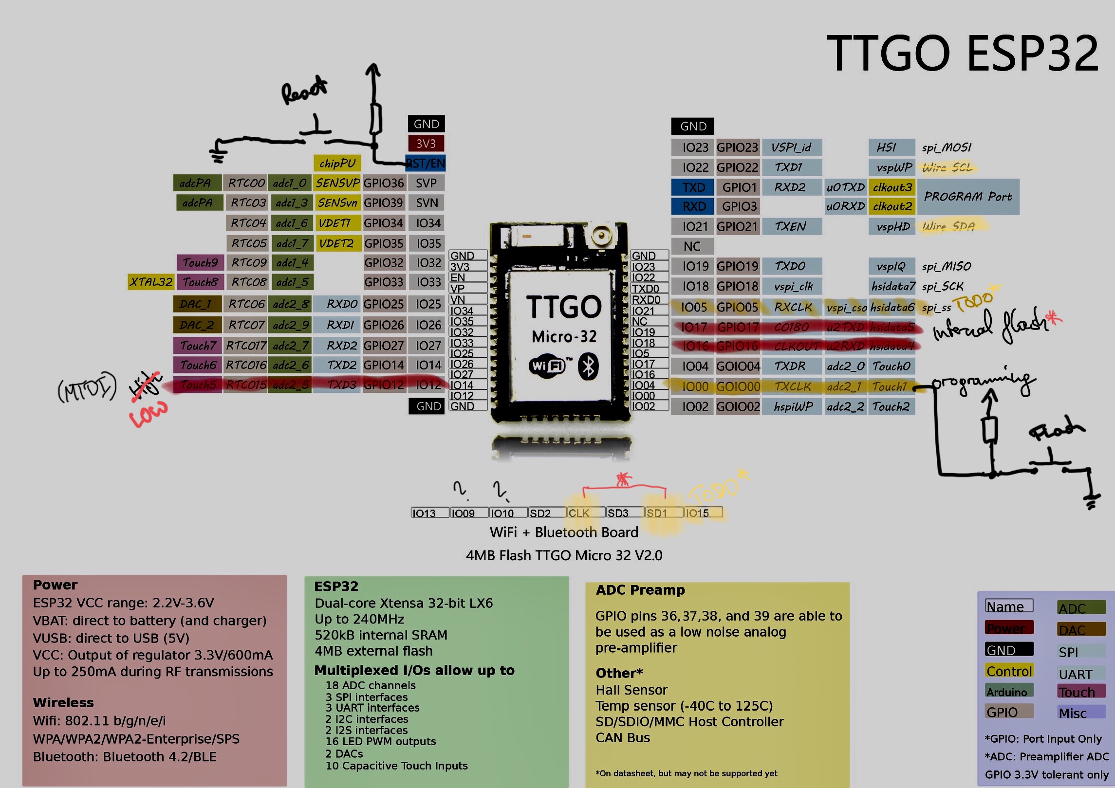
Confusing Pins
When looking at the bottom row of the pins (image above) we have:
GPIO13,GPIO9,GPIO10,SD2,CLK,SD3, SD1,GPIO15.
Considering the schematics from LilyGo’s website we get the following schematics of the module:

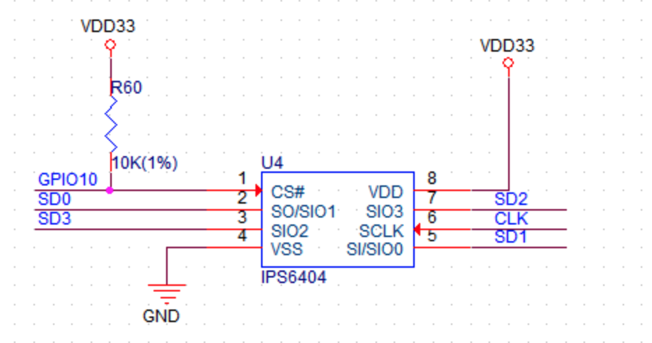
Which translates to the following bottom row:
| ESP32D4 | TTGO32 Micro |
IO13 |
GPIO13 |
SD2 |
GPIO9 |
SD3 |
GPIO10 |
CMD |
SD2 |
CLK |
CLK |
SD0 |
SD3 |
SD1 |
SD1 |
IO15 |
GPIO15 |
As well as
| ESP32D4 | TTGO32 Micro |
IO16 |
CS |
IO17 |
SD0 |
If you need some examples for working mappings of a TTGO T-Micro 32 to SD/GPS/PSRAM/… check the schematics of the Open-Smartwatch, GPS Edition: https://github.com/Open-Smartwatch/open-smartwatch-gps.
SPI
According to the datasheet any pin can be configured for this.
The best resource regarding SPI I could find is this example: https://github.com/espressif/arduino-esp32/blob/master/libraries/SPI/examples/SPI_Multiple_Buses/SPI_Multiple_Buses.ino
The ESP32 has four SPI buses, however as of right now only two of them are available to use, HSPI and VSPI. Simply using the SPI API as illustrated in Arduino examples will use VSPI, leaving HSPI unused.
Which gives us the default VSPI pins (which is correct in the diagram above :) ):
| SPI Pin | GPIO |
|---|---|
SCLK |
18 |
MISO |
19 |
MOSI |
23 |
| ` SS ` | ` 5` |
I2C
According to the diagram the default pins for I2C are IO21/IO22, which overlap with VSPIHD/VSPIWP. But, we can switch the SDA/SCL pins on demand:
// redefine default pins
#define SDA 23
#define SCL 19
See this thread for more details: https://github.com/espressif/arduino-esp32/issues/722
Also: https://github.com/espressif/arduino-esp32/blob/master/libraries/Wire/src/Wire.cpp