Introduction to TTGO ESP8266 Weather Station
Currently, this blog post summarizes my first impressions and steps with this module. I will update this post with more code and examples later.
Table of Contents
The Hardware
You can get the module via https://www.aliexpress.com/item/32854542718.html
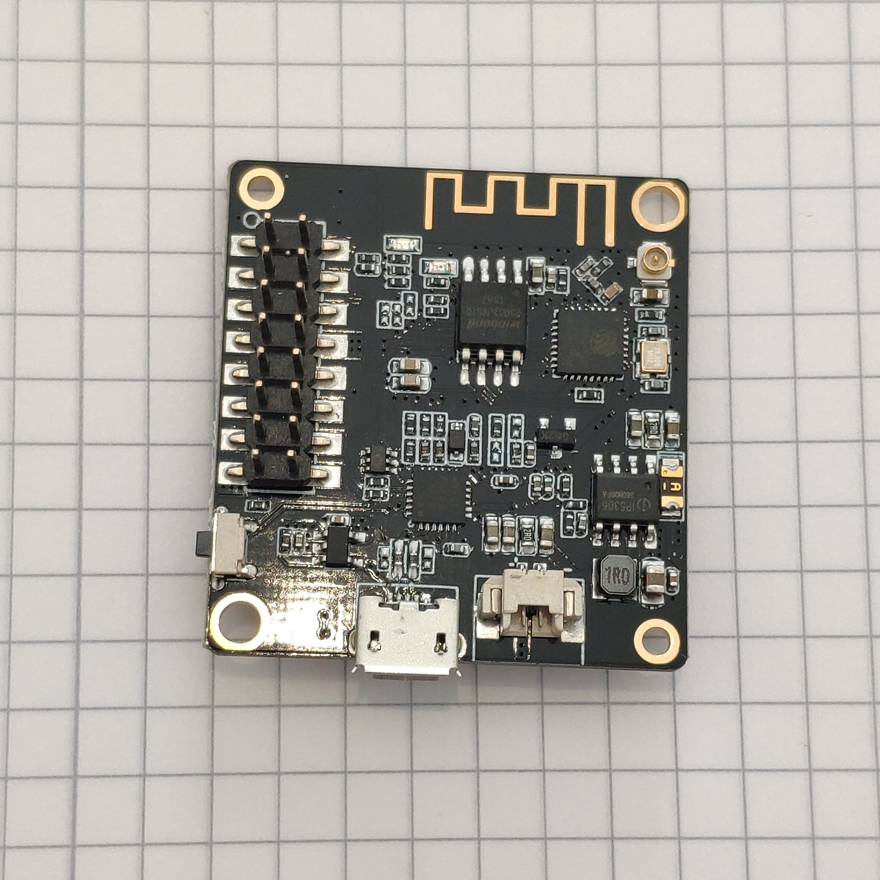
It contains the following components:
- ESP8266 (Datasheet)
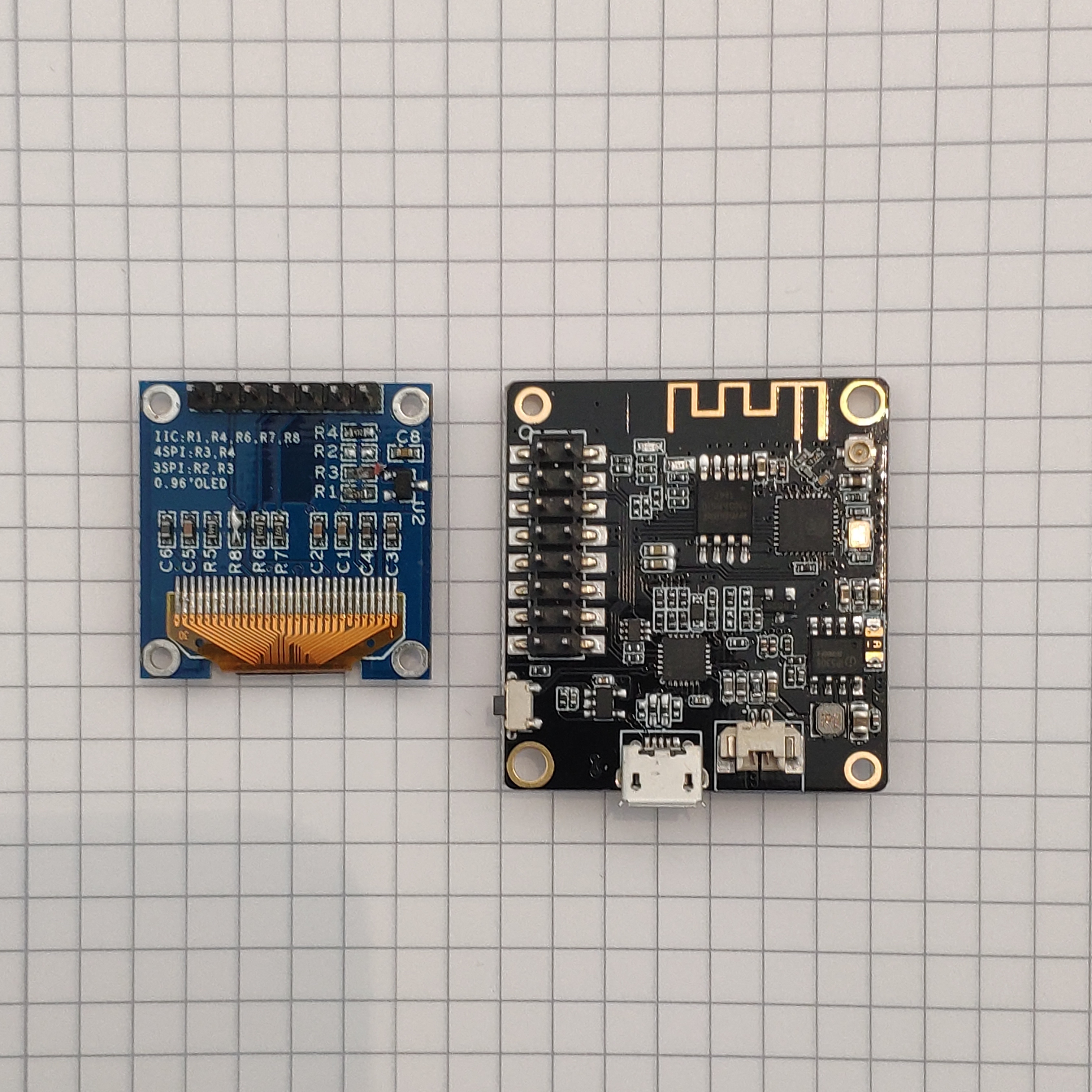
- SH1106 1.3” OLED Display (
D1/5=SDAD2/4=SCL) - 4MB Flash Winbond W25Q32JVSSIQ (Datasheet) (Although it says “A TTGO wifi board with 2MB flash based on ESP-8266EX.” on the product page, it came with this chip, so make sure to check on yours and set the right settings when flashing.)
- SIL2104 USB-to-UART bridge (Datasheet)
- IP5306 Power Regulator/Charger (Datasheet, Chinese), this page has more info: http://www.datasheetcafe.com/ip5306-datasheet-battery-ic/, set to 500mA charge current.
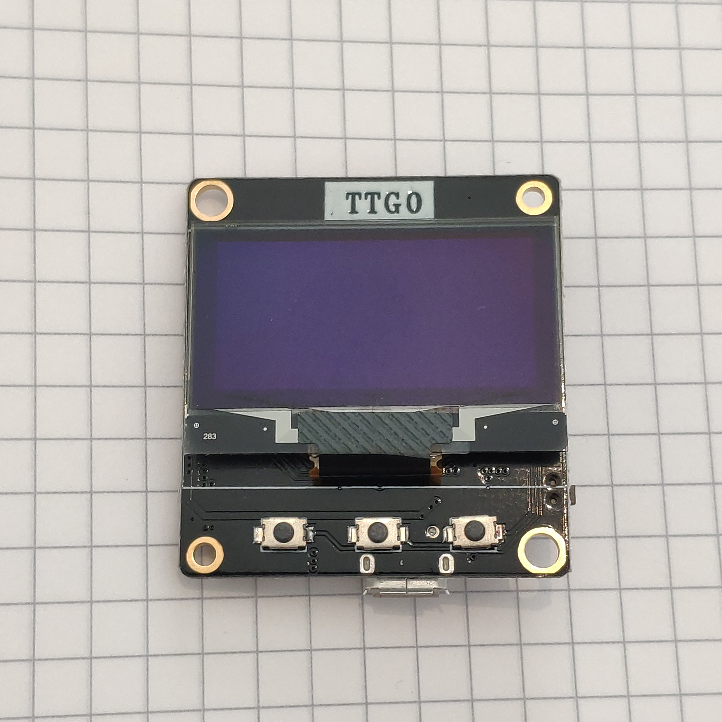
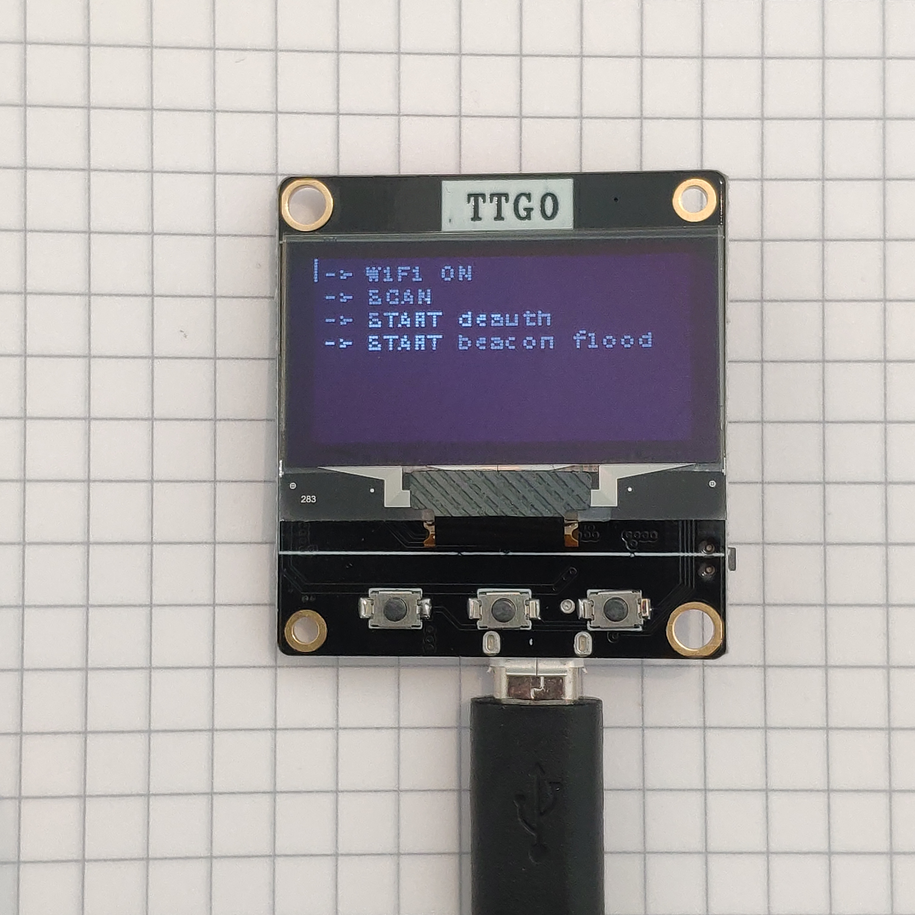
The Buttons
The buttons on the back, as shown in the second picture below.
A0 is closest to the small circle in the top left corner.
A0 |
RST |
IO0/FLASH |
TXD |
IO2 |
RXD |
IO14/CLK |
3V3 |
IO12/MISO |
GND |
IO13/MOSI |
IO16/WAKE |
IO15/CS |
5V |
BAT |
CH_EN |
Images
Click on the images below for high reslution:
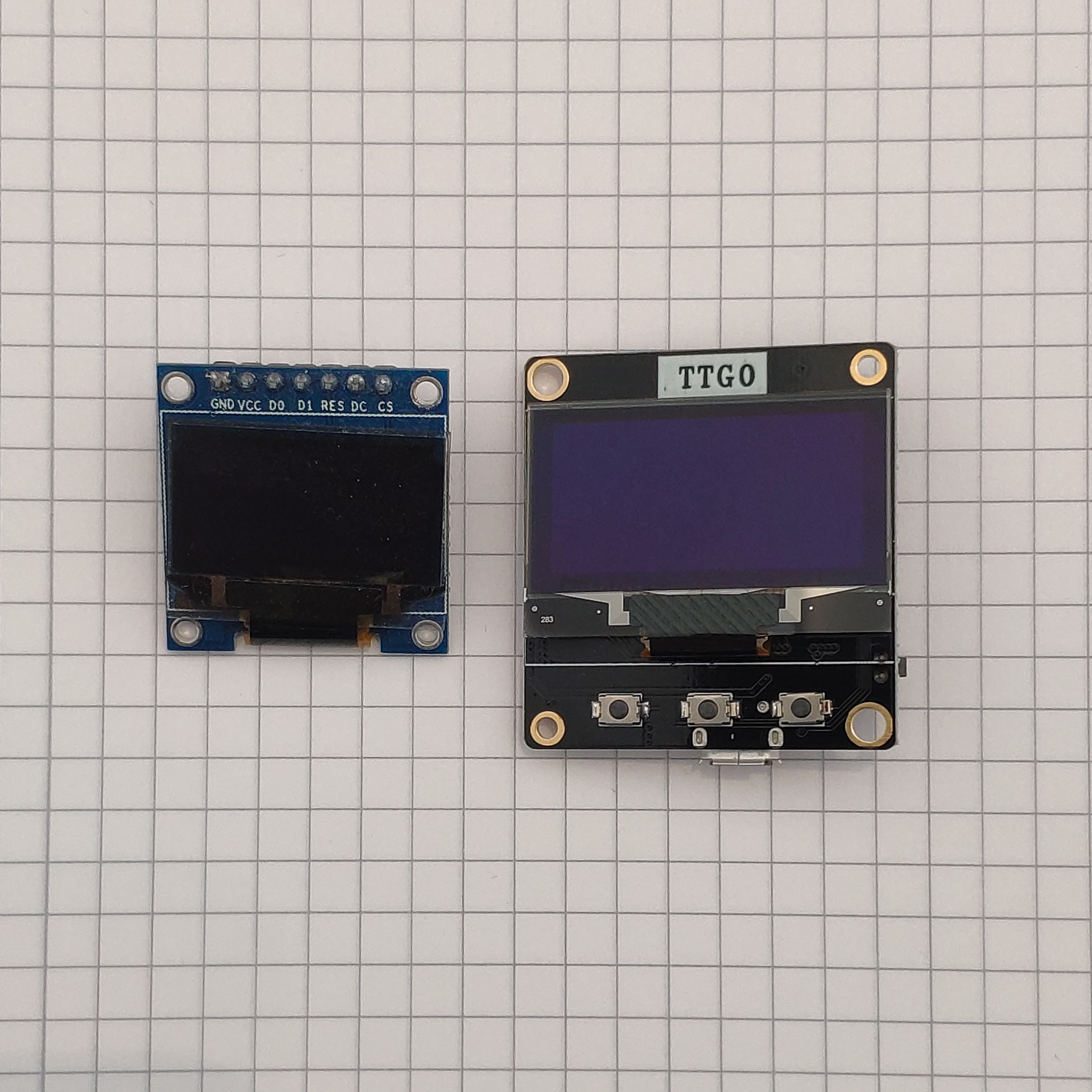
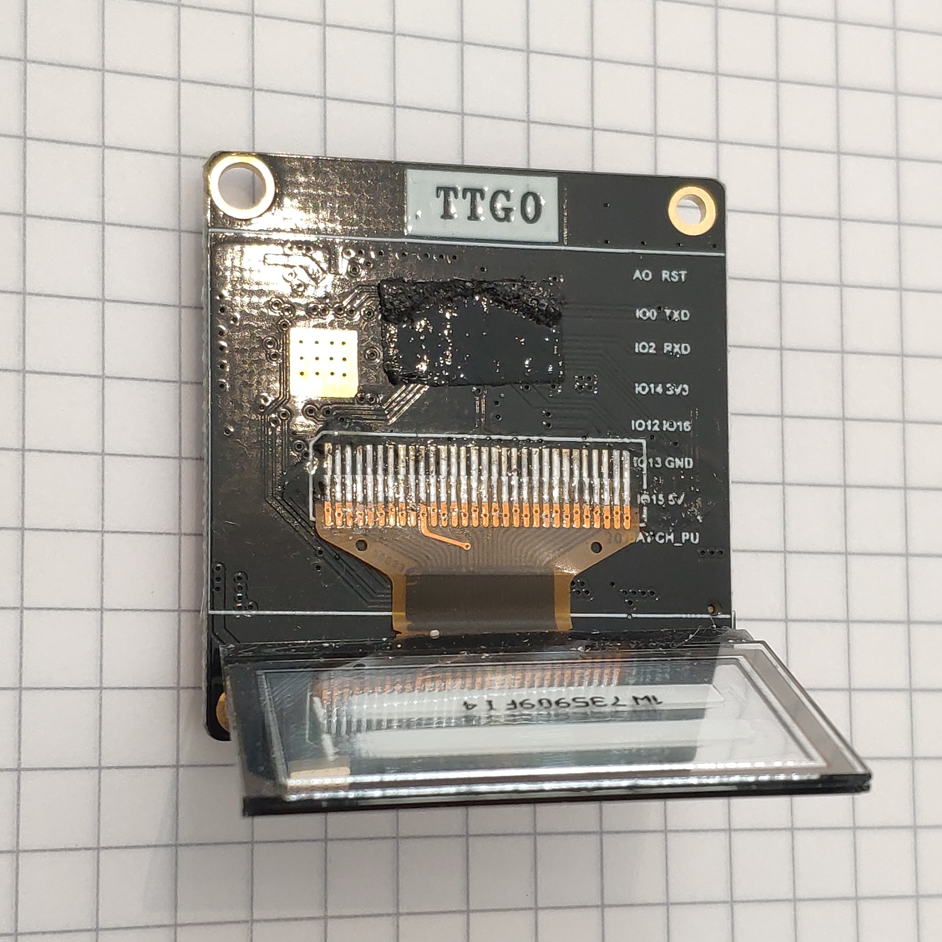
Note:The pins GND/IO16 are not as labeled here, but swapped, see above table.
The Software
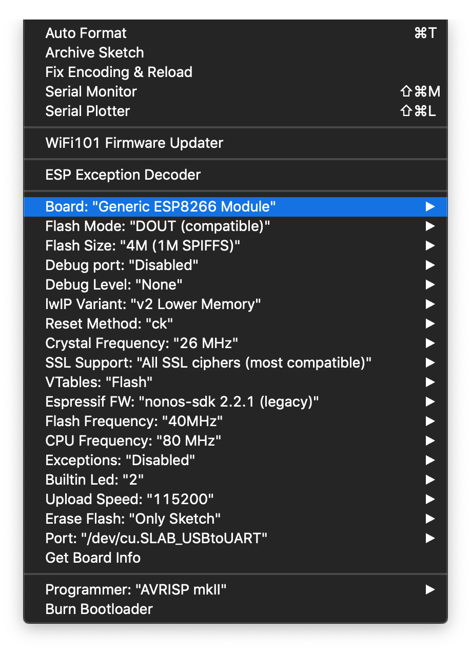
Flashing
Look at the image below to see which settings I used to successfully flash the example:
Provided Example
On the shopping page there is a link pointing to https://github.com/LilyGO/ESP8266_OLED_SH1106/ .
I opened the code with the Arduino IDE. My first compile attempt ended in
/Users/paul/Code/Arduino/sketches/ttgo_weather_station/ttgo_weather_station.ino:29:64: fatal error: SH1106Wire.h: No such file or directory
 #include "SH1106Wire.h" // alias for `#include "SSD1306Wire.h"`
                                                                ^
compilation terminated.
exit status 1
Error compiling for board Generic ESP8266 Module.
I was missing a library. To install it go to the Menu Sketch > Include Library > Manage Libraries and search for ESP8266 and ESP32 Oled Driver for SSD1306 display, and install the library (v4.0).
Click on build again to check if it compiles.
Now it complains about
invalid conversion from 'const char*' to 'const uint8_t* {aka const unsigned char*}' [-fpermissive]
Open the file images.h and change the line 3:
const char WiFi_Logo_bits[] PROGMEM = {
to
const uint8_t WiFi_Logo_bits[] PROGMEM = {
Then, it compiled.
Result
Media ID: B0ImuoIF4KV
Using u8g2
When using the u8g2 library you will need to use the following constructor:
U8G2_SH1106_128X64_NONAME_F_HW_I2C u8g2(U8G2_R0, /* reset=*/U8X8_PIN_NONE);
and initialize the I2C ports differently:
Wire.begin(5, 4);
A minimal working example would be:
#include <Arduino.h>
#include <U8g2lib.h>
#include <Wire.h>

U8G2_SH1106_128X64_NONAME_F_HW_I2C u8g2(U8G2_R0, /* reset=*/ U8X8_PIN_NONE);

void setup(void) {
  // change hardware I2C pins to (5,4) (D1,D2)
  Wire.begin(5,4);
  // init display
  u8g2.begin();
}

void loop(void) {
  u8g2.clearBuffer();         // clear the internal memory
  u8g2.setFont(u8g2_font_ncenB08_tr); // choose a suitable font
  u8g2.drawStr(0,10,"Hello World!");  // write something to the internal memory
  u8g2.sendBuffer();          // transfer internal memory to the display
  delay(1000);
}
I uploaded example code to https://github.com/uvwxy/ttgo-esp8266-ws-u8g2 which demonstrates this module using the u8g2 library (https://github.com/olikraus/u8g2).
See below for the result:
Media ID: B0IreQQl2e5
Using the Buttons
#include <Arduino.h>
#include <U8g2lib.h>
#include <Wire.h>

#define BTN_LEFT 12
#define BTN_MID 14
#define BTN_RIGHT 13

U8G2_SH1106_128X64_NONAME_F_HW_I2C u8g2(U8G2_R0, /* reset=*/ U8X8_PIN_NONE);

void setupButtons() {
  pinMode(BTN_LEFT, INPUT_PULLUP);
  pinMode(BTN_MID, INPUT_PULLUP);
  pinMode(BTN_RIGHT, INPUT_PULLUP);
}

void setup(void) {
  Wire.begin(5, 4); // (CLK,SDA)
  u8g2.begin();
  setupButtons();
}

void loop(void) {
  u8g2.clearBuffer();
  u8g2.setFont(u8g2_font_ncenB08_tr);
  u8g2.drawStr(0, 25, digitalRead(BTN_LEFT) ? "BTN_LEFT: UP" : "BTN_LEFT: DOWN");
  u8g2.drawStr(0, 35, digitalRead(BTN_MID) ? "BTN_MID: UP" : "BTN_MID: DOWN");
  u8g2.drawStr(0, 45, digitalRead(BTN_RIGHT) ? "BTN_RIGHT: UP" : "BTN_RIGHT: DOWN");
  u8g2.sendBuffer();

  delay(50);
}